Fellow programmers,
I know this is a little outside your juridistiction, but I was wondering perhaps if you have time, if you could help me with one "procedure". Not in view of math but what would be the best way to take.
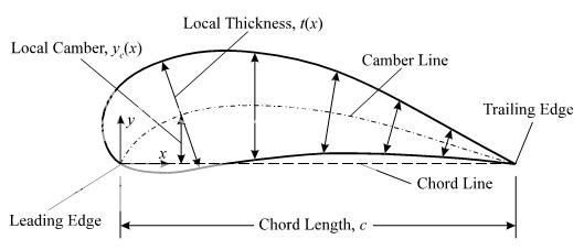

This is an airfoil / profile. Usually, profiles are defined with two sets of data. One is the position of mean camber line, given in the form of x,y where x is usually given in percentages of chord length. Second set of data is thickness at percentages of chord length. Thickness is always drawn perpendicular to the camber line(!), and that gives the profile points.
Now, I have a reverse problem - I have points of a profile, and I need to determine the position of the camber line. Method of interpolation through points can vary, but it doesn't matter, since I can always interpolate as many points as I need, so it comes to linear in the end.
Remember, since the thinkness is drawn perpendicular to the camber line, the position of camber line is not mean between the points of upper and lower line of profile (called the back and face of profile).
Edit (how this is done on paper): Uhh, painfully and in large scale (I'm talking long A0 paper here, that is 1189x5945mm on a large drawing desk. You start by drawing a first camber line (CL) iteration through the midpoints (mean points) between the points of face and back at same x ordinates. After that you draw a lot of perpendicular lines, perpendicular to that CL, and find their midpoints between face and back (those points on face and back will no longer have same x values). Connect those, and that is your second iteration CL. After that you just repeat the second step of the procedure by drawing perpendicular lines onto that 2nd CL ... (it usually converges after 3 or 4 iterations).
2nd Edit: Replaced the picture with one which better shows how the thinkness is "drawn" onto the camber line (CL). Another way of presenting it, would be like picture no.2. If you drew a lot of circles, whoce center points are at the camber line, and whose radiuses were the amounts of thickness, then tangents to those circles would be the lines (would make up the curve) of the profile.
The camber line is not the mean line (mean between the points of face and back); it can coincide with it (therefore usually the confusion). That difference is easily seen in more cambered profiles (more bent ones).
3rd edit - to illustrate the difference dramatically (sorry it took me this long to draw it) between the mean line and camber line, here is the process of how it is usually done "on paper". This is a rather deformed profile, for the reason, that the difference between the two can be more easily shown (although profiles like this exist also).
In this picture the mean line is shown - it is a line formed by the mean values of face and back on the same x coordinates.

In this picture onto the mean line, perpendicular lines were drawn (green ones). Midpoints of those perpendicular lines make up for the 1st iteration of the camber line (red intermittent line). See how those circles fit better inside the airfoil compared to the first picture.

In the picture below the 2nd iteration of the camber line is shown, along with the mean line from the first picture as to illustrate the difference between the two. Those circles are fitting even better now inside (except that first one which flew out, but don't mind him).

From what I can gather from your diagram, the camber line is defined by it being the line whose tangent bisects the angle between the two tangents of the upper and lower edges.
In other words, your camber line is always the mean point between the two edges, but along a line of shortest distance between the top and bottom edges.
So, given the y-coordinates y=top(x) and y=bot(x), why don't you:
<pseudocode>
for each x:
  find x2 where top(x)-bot(x2) is minimized
  camber( mean(x,x2) ) = mean( top(x),bot(x2) )
</pseudocode>
and then interpolate etc.?

Sorry! On second thought I think that should be
find x2 where ( (top(x)-bot(x2))^2 + (x-x2)^2 ) is minimised
obviously you should be minimising the length of that perpendicular line.
Is that right?
I'm new to stack overflow but this is a problem I have worked on quite a bit and thought I would post an alternate approach to the problem. This approach uses the concept of a Voronoi diagram: http://en.wikipedia.org/wiki/Voronoi_diagram Essentially, a map is created which divides the space into regions containing one of the input points (x,y of your airfoil). The important part here is that any point within the region is closest to the input point in that region. The nodes created by this space division are equidistant to at least three of the input points.
Here is the interesting part: three equidistant points from a center point can be used to create a circle. As you mentioned, inscribed circle center points are used to draw the mean camber line because the inscribed circle measures the thickness.
We are close now. The nature of the voronoi diagram in this application means that any voronoi node inside of our airfoil region is the center point of one of these "thickness circles." (This runs into some issue very close to the LE and TE depending on your data. I usually apply some filtering here).
Basic Structure:
Create Voronoi Diagram
Extract Voronoi Nodes
Determine Nodes Which Lie Within Airfoil
Construct Mean Camber Line From Interior Nodes
Most of my work is in Matlab which has built in voronoi and inpolygon functions. As such, I'm not a huge help in developing those functions but they should be well documented elsewhere.
Trailing Edge/Leading Edge Issues
As I am sure you have experienced or know, it is difficult to measure thickness well when close to the LE/TE. This approach will contruct a fork in the nodes when the thickness circle is less than the edge radius. A check of the data for this fork will find the points which are false for the camber line. To construct the camber line all the way to the edge of the foil you could extrapolate your camber line (2nd or 3rd order should be fine) and find the intersection.
If you love us? You can donate to us via Paypal or buy me a coffee so we can maintain and grow! Thank you!
Donate Us With


